Introduction
Industrial automation is transforming modern manufacturing by reducing human intervention, increasing efficiency, and ensuring precision. As part of this project, I worked on automating a didactic manufacturing system, where a workpiece moves through various processing and sorting stages without manual operation. This involved PLC programming, sensor integration, and robotic control to achieve seamless automation.
The system consists of two major sections:
- Processing Station – Where the workpiece undergoes heating, robotic handling, and cutting.
- Sorting Station – Where the workpiece is categorized based on color and directed to appropriate locations.
All operations are controlled via a Human-Machine Interface (HMI), allowing users to interact with the system through predefined stages.
System Overview
The system operates in three modes:
- Home Mode – Resets the system to its initial state.
- Start Mode – Initiates the automatic process, where the workpiece moves through all stages without manual intervention.
- Stop Mode – Immediately halts operations for safety or maintenance.
The automation process is controlled using PLC programming, with multiple sensors and actuators ensuring smooth operation.
Equipment Used
The system consists of a combination of electrical, mechanical, and pneumatic components:
Control System & Sensors
- Programmable Logic Controller (PLC) – Siemens S7 series (or equivalent) for controlling automation sequences.
- Human-Machine Interface (HMI) – Touchscreen interface for user interaction.
- Light Barrier Sensors – Detect workpiece presence at key locations.
- Limit Switches – Used in robotic arms, oven doors, and conveyor belts to determine position.
- Colour Sensor – Identifies the workpiece colour for sorting.
- Rotary Encoder – Tracks conveyor belt movement and workpiece positioning.
Mechanical Components
- Linear Robot – Moves the workpiece from the oven to the turntable.
- Gripper with Suction Mechanism – Picks up and releases workpieces.
- Turntable – Rotates the workpiece between positions (receiving, sawing, and ejection).
- Saw Machine – Cuts the workpiece at a predefined location.
- Conveyor Belt System – Transports workpieces between stations.
Pneumatic & Electrical Actuators
- Solenoid Valves – Control air pressure for gripping, ejecting, and moving components.
- Pneumatic Ejectors – Push sorted workpieces into designated bins.
- Compressors – Provide pressurized air for pneumatic components.
- Stepper Motors & Servo Motors – Drive the conveyor, linear robot, and turntable.
Processing Station: Transforming the Workpiece
Oven
The oven is the first part of the process. It mainly consists of an oven feeder, oven door, oven light, a few limit switches, and light barriers. In the start stage, when a workpiece is placed on the oven feeder, the oven door opens, and the oven feeder retracts into the oven. The oven door then closes immediately. The workpiece remains inside the oven for nine seconds while the oven light blinks, then the oven door opens, and the workpiece stays inside for another six seconds before the oven feeder extends out.
A light barrier on the oven feeder detects the workpiece initially. This triggers the oven door solenoid valve and the oven feeder motor. After the oven feeder retracts, it detects the limit switch at the retracted end of the oven feeder, closes the oven door, and starts blinking the oven light using a series of combined timers. After nine seconds, the oven door solenoid valve triggers, and the oven light goes off using an on-delay timer. Six seconds later, the oven feeder extends, and after detecting the limit switch at the end of the oven feeder, the process comes to a halt. A counter is used to count the number of times the workpiece crosses the light barrier, helping to distinguish between the extending and retracting motions. Counter is set to 1 when workpiece cuts the light barrier for the first time when going into the oven and set to 2 and then reset when it cuts the light barrier for the second time when it comes out of the oven.
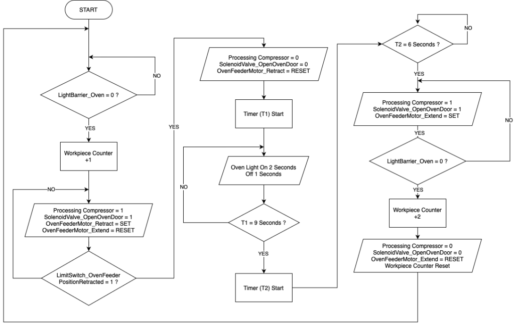
Figure – Flow chart for automatic operation of the Oven
Linear Robot
The linear robot’s task is to carry the workpiece from the oven feeder to the turntable. It moves towards the oven feeder position when it detects the extended oven feeder limit switch and extending motion counter value (When workpiece counter value =2). It stops upon detecting the linear robot oven feeder end limit switch. After picking up the workpiece, it moves towards the turntable until it hits the linear robot turntable end limit switch.
Gripper
The gripper mainly consists of two parts: the gripper mover and the gripper itself. The gripper mover moves up and down to pick up and place back the workpiece, and the gripper uses suction to grip the workpiece. Both functions operate using solenoid valves. The gripper detects its position at the oven feeder using the linear robot limit switch, moves down, grips the workpiece, and moves up. After the linear robot moves to the turntable position, the gripper performs the reverse process. Once the gripper places the workpiece at the turntable, “Work piece at turntable” memory it is set to one to identify the arrival of workpiece at turntable.
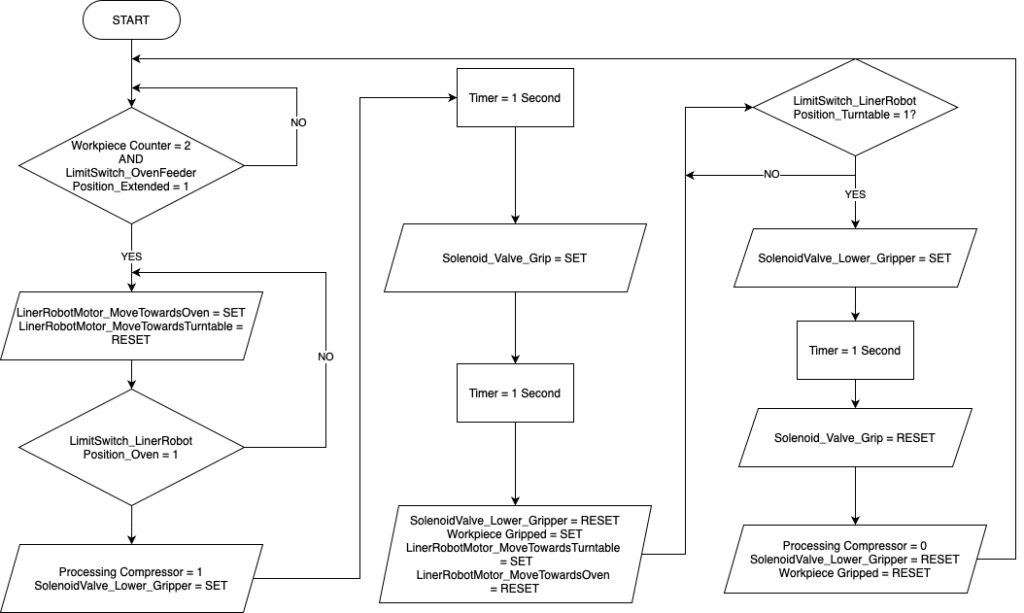
Figure – Flowchart for automatic operation of Linear robot, Gripper, and Gripper Mover
Turntable and Saw
The turntable has three main positions: the linear robot position (where the workpiece is placed onto the turntable), the saw position (where the sawing function occurs), and the conveyor position (where the workpiece is ejected onto the conveyor belt). Operation of the turntable is triggered when “Workpiece at turn table” memory, “Sawed” memory or “Workpiece pushed” memory bit is 1. Limit switches at these three positions help identify the stopping points during the process.
The saw starts working in a sequence of 1 second on and 2 seconds off when the workpiece arrives at the saw position. This is achieved using a pulse train created by two pulse generators and an on-delay timer, running for nine seconds. After nine seconds, the turntable moves to the conveyor position, and the workpiece is ejected onto the conveyor belt using the solenoid valve ejector on the turntable. This action is triggered by the limit switch at the end. The turntable then automatically resets to its linear robot position.
Processing Conveyor Belt
After the workpiece is pushed onto the conveyor belt, it starts moving, triggered by the memory bit “Workpiece Pushed”. The workpiece then travels along the processing conveyor belt and passes onto the sorting conveyor belt. After the workpiece crosses the light barrier at the beginning of the sorting conveyor belt, the processing conveyor belt stops.
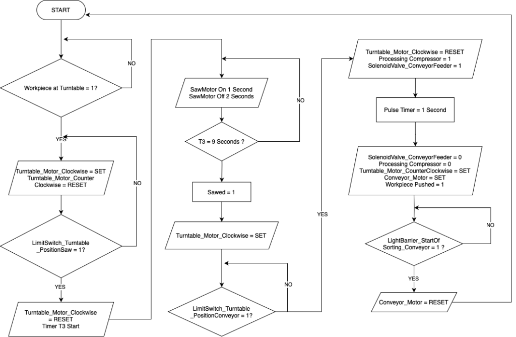
Figure – Flowchart for automatic operation of turntable, saw, processing conveyor and conveyor feeder
Sorting Station
Conveyor Belt and the Encoder
The conveyor belt and the encoder are crucial parts of the sorting station. They help identify the position of the workpiece. The conveyor belt is coupled with an encoder that provides output proportional to the movement of the conveyor. For workpieces to be sorted, red pieces have to stop in front of the three ejectors, while blue and white pieces should continue along the conveyor belt. To identify these four positions, we ran a piece along the conveyor and reset the encoder value at the light barrier in the middle of the conveyor belt. We then started counting the encoder value for each position and programmed the conveyor to stop at those encoder values.
Since the red workpieces should be sorted into C, B, and A positions in a round-robin configuration, we used a counter to detect the red pieces crossing the middle light barrier. According to these counter values, the workpieces stop at the relevant positions. When counter value is 1, to ejector C, when 2, to ejector B and when 3, to ejector A. Once a red coloured work piece is sent to slider A, counter value is reset to zero and sorting process is started again.
Colour Sensor
In this configuration, we need to identify red workpieces and discard other colours. We use a colour sensor to achieve this. The colour sensor provides continuous values corresponding to the colours it detects. It gives us three distinct graphs for the three colours with different minimum values. Using comparators, we isolated a band for each colour’s minimum values. Figures 4,5 and 6 shows 3 graphs obtained from the colour sensor, which were then used to calculate the respective colour bands. Identified colour bands are showed in the table.
| Colour | Minimum Value | Maximum Value |
| Red | 7.1 | 7.5 |
| Blue | 8.05 | 8.35 |
| White | 6.2 | 6.5 |
Colour sensor readings for each colour are given below.
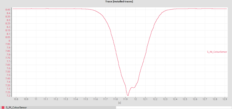
Figure – Sensor graph for red colour
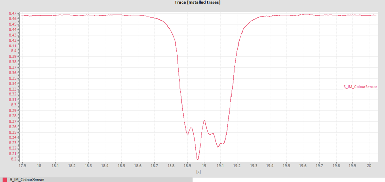
Figure – Sensor graph for blue colour
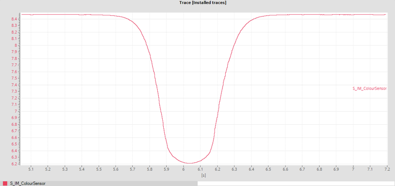
Figure – Sensor graph for white colour
Ejectors
When a red workpiece stops in front of one of the “A,” “B,” or “C” ejectors, it is pushed into the sliders. The ejectors operate based on the signal used to stop the conveyor at their positions using the counter. The light barriers at the bottom of the sliders are then triggered, closing the solenoid valve ejectors. When a work piece is sensed at the slider A, counter value is reset back to 0 and sorting can be started from the beginning.
Compressors
Two compressors in each station are used to power the solenoid valves in the system. They can be explained as follows:
Processing station compressor powers:
- Oven Door
- Gripper Mover
- Gripper
- Turntable Ejector
Sorting station compressor powers:
- Ejector A
- Ejector B
- Ejector C
Each compressor is turned on only when any one of above mentioned component is turned on and it is kept turned off all the other time. Outputs used to trigger each of those elements are used as the triggering signal for compressors. This way, compressors are turned on only when necessary.
Challenges & Solutions
During development, we faced several technical challenges, which were resolved as follows:
1. Color Sensor Variability
• Readings fluctuated across different workstations.
• Solution: Recalibrated sensor settings at each setup.
2. Encoder Position Inconsistencies
• Sorting accuracy depended on encoder values.
• Solution: Manually adjusted encoder values for precision.
3. Ejector Timing Issues
• Initial implementation relied on pulse timers, causing inaccuracies.
• Solution: Reprogrammed ejectors without timers for better control.